Op voorraad Populair product
AXL F DOR4/2 AC/220DC 1F
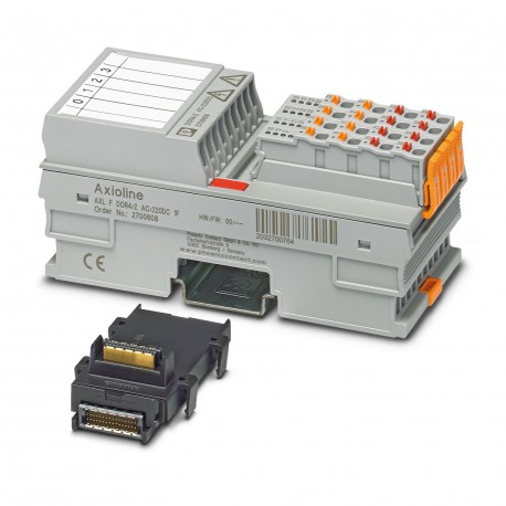
AXL F DOR4/2 AC/220DC 1F 2700608 PHOENIX CONTACT I/O module
$0.00
USD
4692 op voorraad
Belangrijkste specificaties
:
For DC see load limit curve, e.g., the following values:
Type:
block modular
Diepte:
54 mm
Breedte:
53.6 mm
Leveranciersinformatie
Producten: 0
Wordt doorgaans binnen 2-3 werkdagen verzonden.
Kwaliteit gegarandeerd
Snelle verzending
Technische ondersteuning
Technische specificaties
| Parameter | Waarde |
|---|---|
| For DC see load limit curve, e.g., the following values: | |
| Type | block modular |
| Diepte | 54 mm |
| Breedte | 53.6 mm |
| Hoogte | 126.1 mm |
| Stroomverbruik | max. 280 mA (all relays pick up) |
| Producttype | I/O component |
| Montagetype | DIN rail mounting |
| Productfamilie | Axioline F |
| Voedingsspanning | 5 V DC (via bus base module) |
| Verbindingsnaam | Axioline F connector |
| Artikelrevisie | 02 |
| Vervuilingsgraad | 2 |
| Striplengte | 8 mm |
| Verbindingsmethode | Bus base module |
| Montagepositie | any (observe temperature and current derating) |
| Aantal uitgangen | 4 (floating) |
| Omvang van de levering | including bus base module and Axioline F connectors |
| Schakelstroom | max. 8 A AC (cos phi = 1) |
| Invoeradresgebied | 0 Byte |
| Opmerking over afmetingen | The depth applies when a TH 35-7.5 DIN rail is used (in accordance with EN 60715). |
| Schakelcapaciteit | max. 2000 VA |
| Transmissiesnelheid | 100 Mbps |
| Maattekening | |
| Opmerking over de aanvraag | Only for industrial use |
| Uitvoeradresgebied | 1 Byte |
| Schakelfrequentie | max. 6 (per minute) |
| Beschermingsgraad | IP20 |
| Aantal interfaces | 2 |
| Overspanningscategorie | III (EN 61010-2-201/UL 61010-2-201), up to 2000 m above sea levelII (EN 61010-2-201/UL 61010-2-201), up to 3000 m above sea level |
| Standaardaanduiding | Ambient conditions |
| Verbindingstechnologie | 2-conductor |
| Contactschakeltype | N/O contact |
| Mechanische levensduur | 10x 106cycles |
| Vereiste parametergegevens | 1 Byte |
| Luchtdruk (werking) | 70 kPa ... 106 kPa (up to 3000 m above sea level) |
| Normen/specificaties | IEC 61850-3 |
| Geleiderdoorsnede AWG | 24 ... 16 |
| Vereiste configuratiegegevens | 6 Byte |
| Geleiderdoorsnede stijf | 0.2 mm² ... 1.5 mm² |
| Opmerking over de verbindingsmethode | Please observe the information provided on conductor cross sections in the “Axioline F: system and installation” user manual.When selecting the cables, please note that in the case of a small conductor cross section and high current, the terminal point temperature may be up to 30 K above the ambient temperature. |
| Dwarsdoorsnede van een geleider, stijf | 0.2 mm² ... 1.5 mm² |
| Omgevingstemperatuur (bedrijfstemperatuur) | -25 °C ... 60 °C (max. 6 A/channel for wall mounting on horizontal DIN rail; max. 4 A/channel for any mounting position) |
| Luchtdruk (opslag/transport) | 70 kPa ... 106 kPa (up to 3000 m above sea level) |
| Flexibele doorsnede van de geleider | 0.2 mm² ... 1.5 mm² |
| Toegestane luchtvochtigheid (tijdens gebruik) | 5 % ... 95 % (non-condensing) |
| Doorsnede van een geleider, flexibel | 0.2 mm² ... 1.5 mm² |
| Testspanning: Relaiscontact / logica | 4 kV |
| Omgevingstemperatuur (opslag/transport) | -40 °C ... 85 °C |
| Toegestane luchtvochtigheid (opslag/transport) | 5 % ... 95 % (non-condensing) |
| Maximaal vermogensverlies onder nominale omstandigheden | 1.4 W |
| Testspanning: Relaiscontact / functionele massa | 4 kV |
| Schakelcapaciteit conform IEC 60947-5-1 | 6 A (120 V (AC15)) |
| Testspanning: Relaiscontact/relaiscontact (open contact) | 1 kV, 50 Hz, 1 min. |
| Testspanning: Relaiscontact/relaiscontact (aangrenzende mannelijke connectoren) | 2.5 kV |
Productbeschrijving
AxiolineF, Relay module, Relay outputs:4 (potential-free), Open contact, 220 VDC, 230 VAC, local bus transmission rate:100 MBit/s, protection index: IP20, including bus socket module and AxiolineF con
Belangrijkste kenmerken
- Industriële kwaliteit
- RoHS-conform
- CE-gecertificeerd
- 1 jaar garantie
Productdocumenten
Gegevensblad
Technische specificaties en prestatiegegevens
Gebruikershandleiding
Installatie- en bedieningshandleiding


