Op voorraad Populair product
MINI MCR-SL-U-I-0
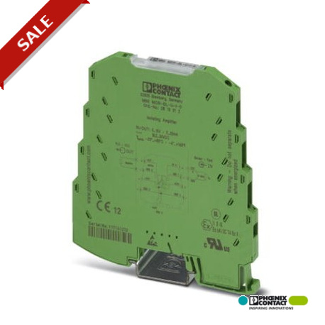
MINI MCR-SL-U-I-0 2813512 PHOENIX CONTACT MCR 3-way isolating amplifier, for electrical isolation of analog ..
$0.00
USD
4075 op voorraad
Belangrijkste specificaties
:
Class I, Div. 2, Groups A, B, C, D T5 applied for
GL:
GL EMC 2 D
ATEX:
Ex II 3 G Ex nA IIC T4 Gc X
Kleur:
green
Leveranciersinformatie
Producten: 0
Wordt doorgaans binnen 2-3 werkdagen verzonden.
Kwaliteit gegarandeerd
Snelle verzending
Technische ondersteuning
Technische specificaties
| Parameter | Waarde |
|---|---|
| Class I, Div. 2, Groups A, B, C, D T5 applied for | |
| GL | GL EMC 2 D |
| ATEX | Ex II 3 G Ex nA IIC T4 Gc X |
| Kleur | green |
| Diepte | 102.5 mm |
| Breedte | 6.2 mm |
| Hoogte | 93.1 mm |
| Conformiteit | CE-compliant |
| Aanduiding | Electromagnetic RF field |
| Schroefdraad | M3 |
| Geluidsemissie | EN 61000-6-4 |
| Geluidsimmuniteit | EN 61000-6-2 When being exposed to interference, there may be minimal deviations. |
| Aantal kanalen | 1 |
| Bouwmateriaal | PBT |
| Aantal ingangen | 1 |
| Vervuilingsgraad | 2 |
| Striplengte | 12 mm |
| UL, VS / Canada | UL 508 Recognized |
| Verbindingsmethode | Screw connection |
| Montagepositie | any |
| Aantal uitgangen | 1 |
| Stroomverbruik | < 450 mW |
| Maximale ingangsspanning | 30 V |
| Maximale uitgangsstroom | 28 mA |
| Beschermingsgraad | IP20 |
| Elektrische isolatie | Basic insulation according to EN 61010 |
| Overspanningscategorie | II |
| Voedingsspanningsbereik | 19.2 V DC ... 30 V DC (The DIN rail bus connector (ME 6,2 TBUS-2 1,5/5-ST-3,81 GN, Order No. 2869728) can be used to bridge the supply voltage. It can be snapped onto a 35 mm DIN rail according to EN 60715)) |
| Spanningsingangssignaal | 0 V ... 10 V |
| Montage-instructies | The T connector can be used to bridge the supply voltage. It can be snapped onto a 35 mm DIN rail according to EN 60715. |
| Huidig uitgangssignaal | 0 mA ... 20 mA |
| Normen/voorschriften | EN 61000-4-3 |
| Grensfrequentie (3 dB) | approx. 100 Hz |
| Nominale voedingsspanning | 24 V DC |
| Staprespons (10-90%) | approx. 3.5 ms |
| Maximaal stroomverbruik | < 20 mA |
| Nominale isolatiespanning | 50 V AC/DC |
| Configureerbaar/programmeerbaar | no |
| Maximale transmissiefout | ≤ 0.1 % (of final value) |
| Elektromagnetische compatibiliteit | Conformance with EMC Directive 2004/108/EC |
| Omgevingstemperatuur (bedrijfstemperatuur) | -20 °C ... 65 °C |
| Belasting/uitgang belastingsstroom uitgang | ≤ 500 Ω |
| Maximale temperatuurcoëfficiënt | < 0.01 %/K |
| Maximale AWG-doorsnede van de geleider. | 12 |
| Geleiderdoorsnede min. AWG. | 26 |
| Temperatuurcoëfficiënt, typisch | < 0.002 %/K |
| Ingangsweerstand van de spanningsingang | approx. 100 kΩ |
| Testspanning, ingang/uitgang/voeding | 1.5 kV (50 Hz, 1 min.) |
| Maximale doorsnede van de geleider (massief). | 2.5 mm² |
| Dwarsdoorsnede van de geleider, massief, minimaal. | 0.2 mm² |
| Flexibele maximale doorsnede van de geleider. | 2.5 mm² |
| Flexibele doorsnede van de geleider, minimaal. | 0.2 mm² |
| Omgevingstemperatuur (opslag/transport) | -40 °C ... 85 °C |
| Typische afwijking van het meetbereik, eindwaarde | 5 % |
Productbeschrijving
More details
Belangrijkste kenmerken
- Industriële kwaliteit
- RoHS-conform
- CE-gecertificeerd
- 1 jaar garantie
Technische details
The 6.2 mm wide standard signal 3-way isolating amplifier MINI MCR-SL-U-I-... is used for electrical isolation, conversion, amplification and filtering of standard signals.
Productdocumenten
Gegevensblad
Technische specificaties en prestatiegegevens
Gebruikershandleiding
Installatie- en bedieningshandleiding


